meta data for this page
The Main Interface
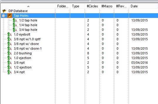
The Main Interface is made up of three different sections the list of patterns, the pattern information, and a view of what the pattern looks like.
List Section

The first window to the left of the main interface is the list of patterns that have been made. Here is where they can be organized, folders can be made and patterns under those folders. Patterns can also be copied, deleted, or renamed.

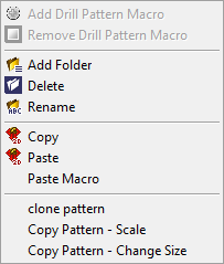
If the user right clicks on a pattern this menu will come up, the three top sections are the same as those on the ribbon. The last section allows you more options.
Clone Pattern – using this option will clone the pattern and it will be identical.
Copy Pattern Scale – this option will clone the pattern but allows the user to scale it by a scale factor changing all circle to that scale factor.
Copy Pattern Change Size – this option will clone the pattern but allow the user to change the size of all the circle by a given amount. This amount that is given will increase the diameter of each circle incrementally.
Pattern Information
The pattern information section is made up of two different areas the pattern information and the macro information.
Pattern Information Area

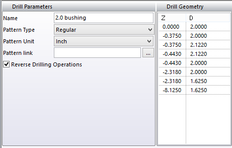
In this area you have all the information about the pattern that was created.
Name– this is the name that the pattern was given to make it recognizable and understandable to the operator,
Pattern Type – here there are three choices making the proper choice when creating the pattern will tell the system how to use this pattern for checking.
Regular Pattern – this setting you will use for holes that are not going to be part of a circuit that need to be sealed.
Water Line and Oil Line – this setting will need to be use when the hole is part of a sealed circuit, each one will put that pattern in a category. This will allow the user to check and see if there are any intersections in between the two circuits that should not be there. See the Drill Tab section for more details.
Pattern Unit – allows the user to switch from inch to metric.
Pattern Link – here a file can be linked to individual patterns that have additional information or notes, this can be a picture or word document.
Reverse Drilling Operation – with this checked it allows the pattern to be drilled either end, this is used for holes that go through the work piece.
Drill Geometry – is a list of circle diameters in order that make up the pattern.
Macro Information Area
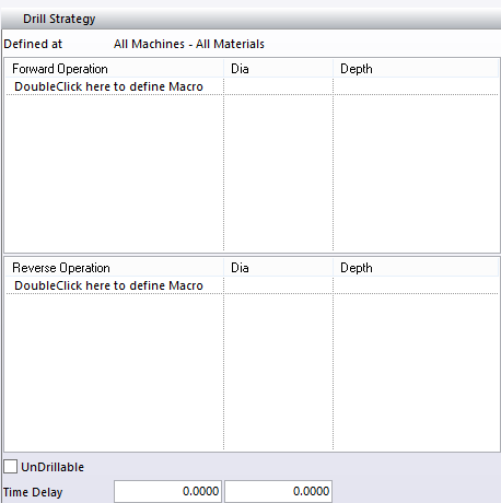
In this area you have all the information about the macro, you can

Defined at – this shows what level the macro was created at.
Forward Operation – here will be a list of the operations that were used to create the macro if one exists. Here it will start at the larges end of the pattern calling that the forward end.
Reverse Operation – here will be a list of operations that were used to create the macro from the opposite end.
UnDrillable – with this checked the pattern will not show the macro in the drilling interface.
Double clicking in the Forward or Reverse Macro area to create a macro to be used.