meta data for this page
General Functions
 With these two Functions the user has the ability of editing, manipulating, or getting information on Mill files or posted files.

Under the Mill button in the Milling tab, only the functions that can be used in Milling for the program selected, will be the ones that will be available, these operations will be explained below.

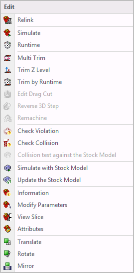
These are the options that are available in the drop down menu of the Mill Button.
Relink – this will display the program page of the program that is selected. It will allow the user to change only certain options in the program page without having to recalculate the program. Those options that are available to change are not greyed out. Simulate – will simulate the toolpath.
Runtime – will give the approximate runtime of the toolpath that are highlighted.
Multi Trim – allows the user to trim the toolpath if it has cut any areas that are not needed to be cut.
Trim Z Level – allows the user to trim the toolpath by giving it the value of where to stop the program and gives the option to save the toolpath in sections.
Trim by Runtime – allows the user to put in a time value or a length of where to have the toolpath trimmed to.
Edit Drag Cut – allows the user to select the parts of the Drag Cut to keep.
Reverse 3D Step – give the user the ability to reverse the direction of any 3D Step toolpath.
Remachine – allows the user to make a Remachine toolpath for any 2D Pocket program.
Check Violations – allows the user to check the toolpath for violations.
Check Collision – allows the user to check the toolpath for Collisions.
Collision test against the Stock Model – allows the user to check for collisions with the stock model.
Simulate with Stock Model – allow the user to run a simulation on the stock model to be able to see how it will cut the steel.
Update the Stock Model – allows the user to update the stock model with any toolpath.
Information – will give the user the information on the parameters that were used to create the toolpath.
Modify Parameters – allows the user to change some of the parameters that were used to create the toolpath.
View Slices –view the toolpath by each individual pass.
Attributes –change the way the toolpath is displayed.
Translate –move any tool path if needed.
Rotate –rotate any toolpath if needed.
Mirror –mirror any toolpath if needed.

Under the ISO button in the Milling tab, only the functions that can be used in ISO for the program selected will be available. These operations are being explained below.

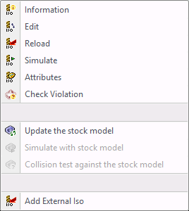
Information – this will give the units the program was posted in, INCH or METRIC, and if the program was violation checked.
Edit this opens the posted file with WordPad to allow changes if needed.
Reload - this option will refresh the screen.
Simulate - this option can simulate the posted program. It will not simulate as a shaded tool or with the head of the machine.
Attributes – this option will change the appearance of the posted file on the screen. Selecting this option will display the Iso file attributes window. The feed or rapid can be turned on or off and also change the colors. The display option has a drop down menu that will give more options as shown here.

Line - will display the program in a line to the color it is set to.
Point - will display the program in points to the color it is set to.
Both - will display the program in both line and points to the color it is set to.
Check Violation - check violation can run the posted program through the simulator to see if the posted file violates the part.
Update the stock model - click on this option and it will update the stock model with the posted file.
Add External Iso - this option will import any posted file. If there is a posted file from another machine that is needed for reference import it using this option. Select the option and a Load window will be displayed. Go to the directory, select the file, and select Open at the bottom right. The program will open in the Iso window to the far right.