meta data for this page
Cad Curves
Cad Curves are construction curves to help the user build feature to aid in the manufacturing of the component being built. Under this icon the user can modify those cad curves.

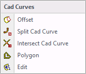
When selecting Cad Curves, the drop down menu shown to the left will be displayed allowing the user to modify or create cad curves.
Offset
The user has the ability to offset a cad curve by a specific amount.
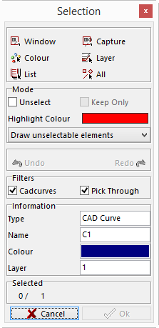
The Selection window will be displayed and the user will select the cad curve to be offset.
Once selected, the Offset Element window will be displayed with parameters that must be completed.
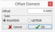
Offset – this value is the amount the offset curve is to be from the original.
RIGHTDIR – will offset the curve to the right of the original.
LEFTDIR – will offset the curve to the left of the original.
Arrows will indicate which is the right or left side as shown below.
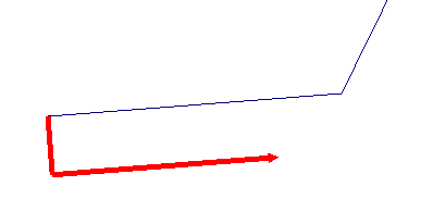 This arrow indicates the curve will be offset to the right.
Split Cad Curves
The user is able to split the cad curve into many equal cad curves. The user can specify the number of curves to make out of one cad curve.

With this option the Selection window will be displayed. Select the cad curve to be split.
Once the curve is selected the Split window will be displayed. Input the number of curves to split the cad curve into and select OK. This will divide the selected curve into equal parts to match the number that was given.
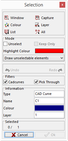


With this option the user can break Cad Curves that cross each other at their intersecting point.
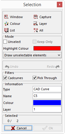
With this option the Selection window will be displayed. The user will need to select the two Cad Curves that cross each another.
Once the two Cad Curves are selected click the OK button and the system will break them at their intersection point.
Polygon
The user can create a cad curve by drawing a polygon line.
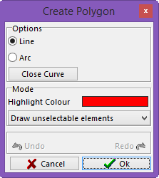
When using this option, the Create Polygon window will be displayed. The user can draw a line on the screen by using this option.
Line - will create straight lines from one point to another.
Arc –select the aproximate center of the radius and the end point and it will create a radius.
Highlight Color - clicking on the color button will bring up the color palette. The user can select the color for the previewed lines.
When selecting Draw unselectable elements, a drop down menu will appear with the following selections.
Draw unselectable elements – will show all elements that cannot be selected.
Hide unselectable elements – will hide all elements that cannot be selected.
Gray unselectable elements – will make all elements that ca not be selected gray.
In the last section of this window there is an Undo button and a Redo button. This will allow the user to back up on the selection to modify a selected point.
Once the shape is created click the right mouse button. This will close the shape by joining the first point and the last point together with a straight line, or leave it as an open curve. Once selected click on the OK button and the curve is created.
 This is an example with the curve left open
 This is an example with the curve closed
Edit Cad Curves
With this option the user can create cad curves by using the Curve Editor window.


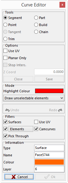
Once selected, the Curve Editor window will be displayed giving the user all options to create a cad curve.
Use the options to build the curve and then click the OK button. The elements selected will become a curve.