meta data for this page
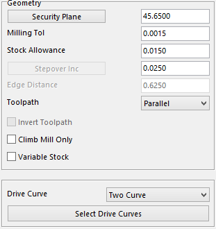
Geometry Section
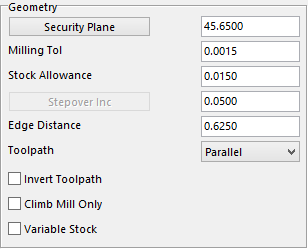
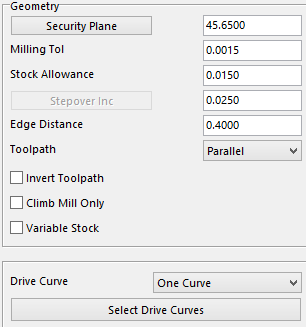
Security Plane – is the safe height that the user wants to start at.
Milling Tol – this tolerance will help to determine the finish on the part. The smaller the value the more points on the toolpath.
Stock Allowance –the value for how much stock the user wants to leave on the work piece.
Stepover Inc – this value is the amount the user wants the tool to Stepover or the amount of material to take per pass.
Edge Distance – this value is the distance the user wants the tool to travel from the selected curve.
Toolpath –there is a drop-down menu that allows the user to select from Parallel or Perpendicular to change the direction of the toolpath.
Invert Toolpath – with this option unchecked the toolpath will start at the curve and move away from it. If this option is checked the toolpath will start at the furthest point and move towards the curve.
Climb Cut Only – this option forces the toolpath to climb cut the work piece.
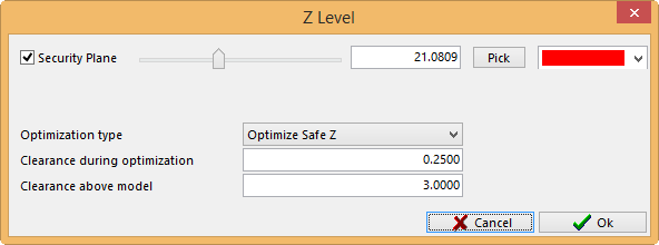
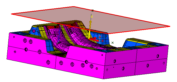
Security Plane Setting
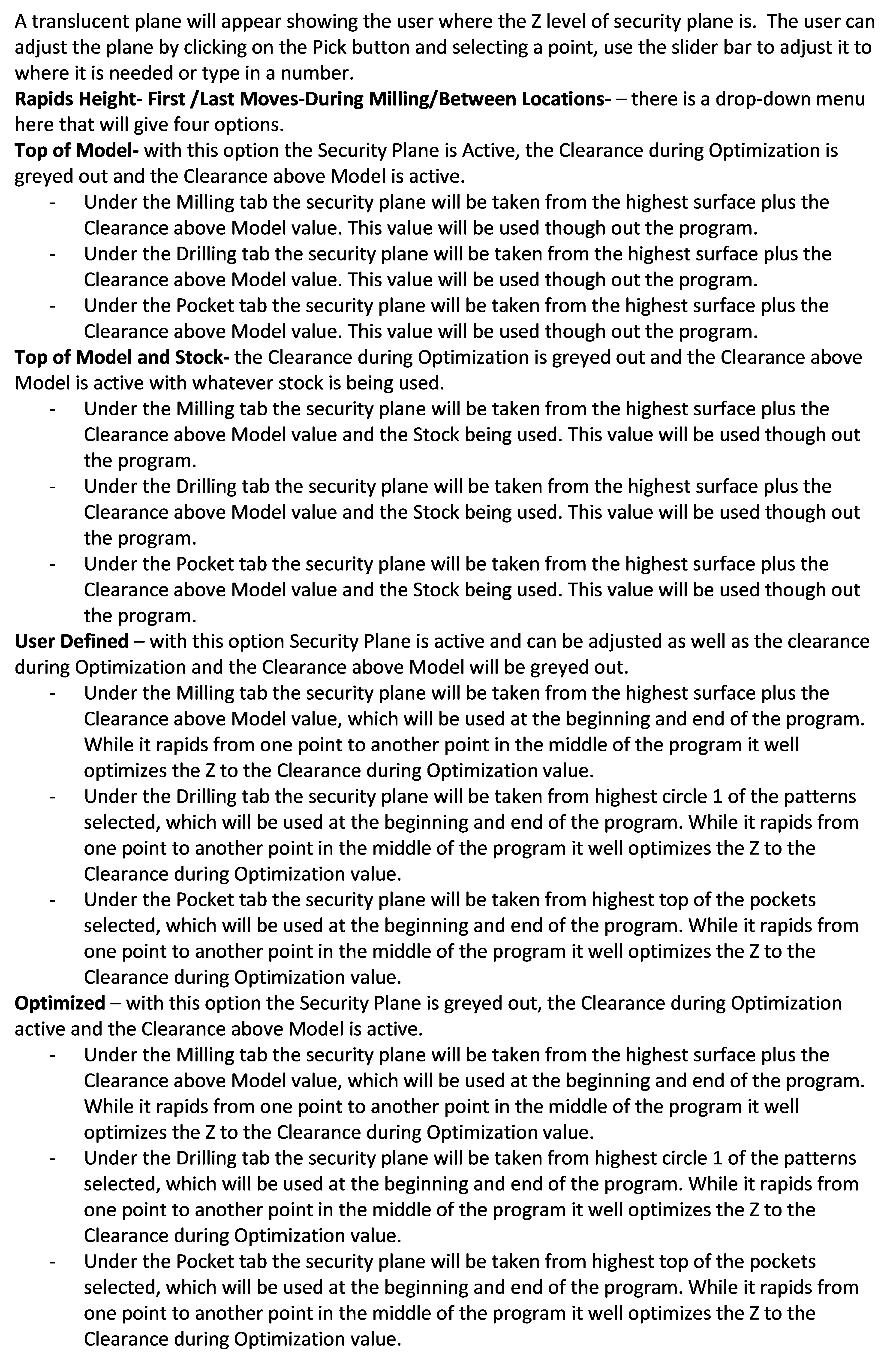
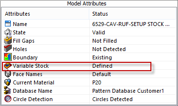
Variable Stock –– this option is filed under the Model tab shown here. Right click on the Variable Stock to display the color palette. Fill in the stock allowances to leave on the color of choice. The user can leave different stock allowances on different colors.
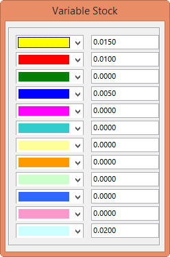
Checking this box in the Geometry Section will bring up the Variable Stock window that was filled in to show what stock allowance is assigned to what color. This option is only active if the box is checked.

In the Drive Curve section, the user is able to select the type of toolpath to use and select the drive curves to be used.

Under Drive Curve the user has four different option to choice from giving the user the ability to change the toolpath direction and the method of toolpath will be created.
S elect of Drive Curves - this lets the user select one or two curves that for the toolpath to follow.
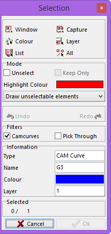
By selecting Select Drive Curves, the selection window will appear allowing the user to select the desired curve to be used. Once that curve is selected click the OK button at the bottom right corner of the window. The user must now select what way, side of the curve to cut on, along with the direction they want the tool to travel. They may even select to cut on the curve making a single line pass. There will be six different selections to choose from which are shown in the pictures below.
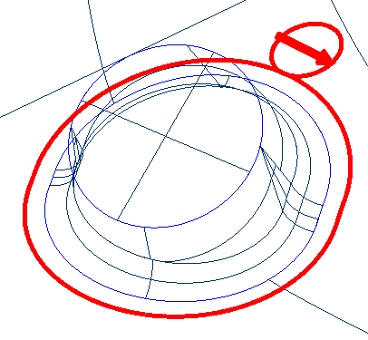
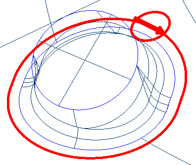
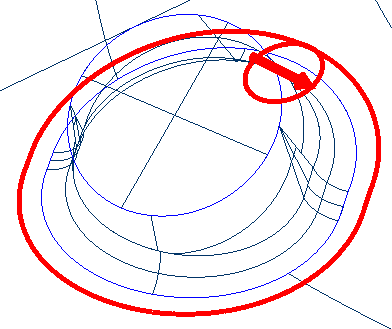
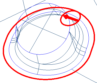
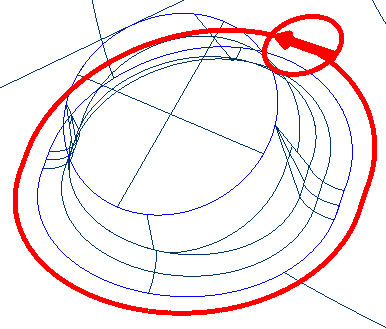
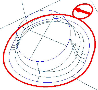
One curve is used with an Edge distance of .400 and a Stepover of .025.
In the diagram the toolpath starts at the selected curve and goes as far as .400 away from the selected curve parallel to that curve with the Toolpath on Parallel.
If the Toolpath is on Perpendicular the toolpath will travel the same distance from the curve but perpendicular to the curve.
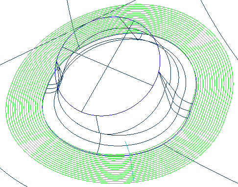 Parallel
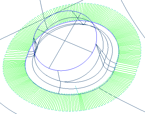 Perpendicular
Two curves (with two curves there is no Edge Distance needed it will use the two curve to get the distance) were used with a .025 Stepover.
In the diagram the toolpath is stepping over a consistent .025 regardless if it is on a vertical or horizontal wall. The operator needs to be careful where the Pattern Machining Program is being used.
If the Toolpath is on Parallel the toolpath will travel Parallel between the two curves.
If the Toolpath is on Perpendicular the toolpath will travel Perpendicular between the two curves.
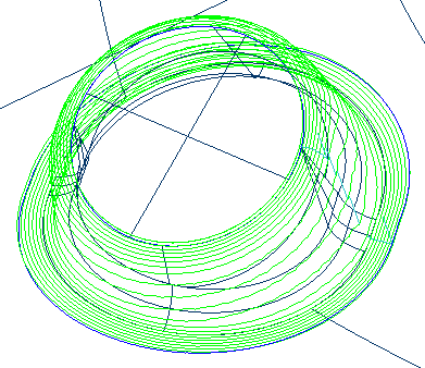 Parallel
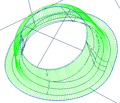 Perpendicular
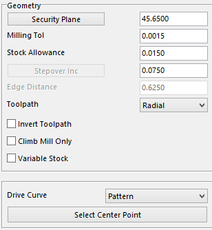
This section explains Pattern with a Radial Toolpath. The system will prompt the user to pick a center point to have the toolpath to revolve around. It will use this point and the toolpath will travel perpendicular from this point to the selected curve. The Stepover value that is used will be executed at the curve.
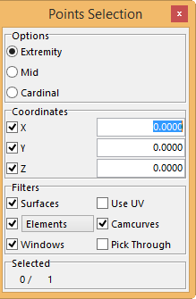
After selecting Select Center Point this is the window that will be displayed. The user will have different options to select the point.
Extremity –will pick surface edges at the end of the UV lines and end points of curve.
Mid – will select the middle of curves or select Use UV in the Filter options and select the middle of the UV lines of the surfaces.
Cardinal – will give the use the ability to select points along the surface edges and the curves.
Coordinates – allows the user to input the location manually\\.
Filters – allows the user to narrow his or her selection to specific elements.
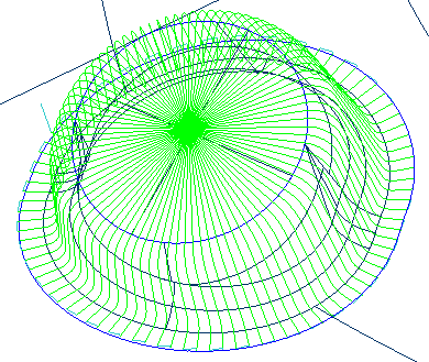
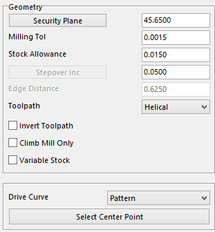
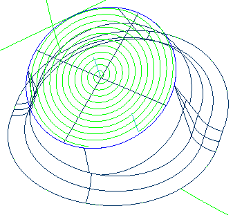
This section explains Pattern with a Helical Toolpath. The system will prompt the user to pick a center point for the toolpath to use as the start point of the Helical. The toolpath will travel around the point selected in a clockwise direction from this point to the selected curve.
The Stepover is the value between each revolution.
The toolpath will start at the curve and work its way to the selected point in a spiral. If the user wants to start at the point and work to the curve check the Invert Toolpath option to reverse the direction of the toolpath.
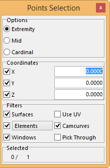
Once you click on Select Center Point this will be displayed. The user will have different options to select the point.
Extremity –will pick surface edges at the end of the UV lines and end points of curve.
Mid – this will select the middle of curves or select Use UV in the Filter options and select the middle of the UV lines of the surfaces.
Cardinal – will give the user the ability to select points along the surface edges and the curves.
Coordinates – allows the user to input the location manually.
Filters – allows the user to narrow the selection to specific elements.
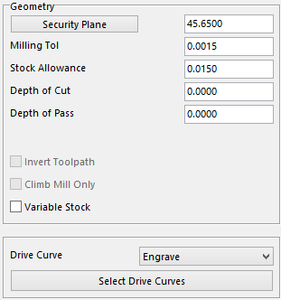
This option explains Engrave. This program will cut directly on the curve and at the same time follow the surface contours of the work piece.
The toolpath can also be made to cut into the work piece by using Depth of Cut and Depth of Pass. The user can input the depth value to go and the amount of material to remove per pass.
The tool will travel on the curve in the same direction that the curve was made. The curve needs to be created in the same direction the user wants the tool to travel.
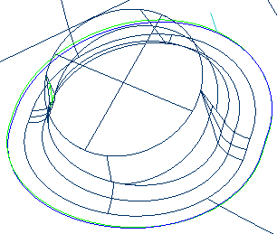 No Depth
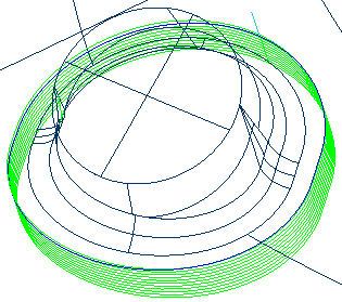 With Depth