meta data for this page
Geometry Section
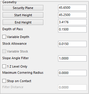
Security Plane – the safe height that the user wants to start at.
Start Height – the value that the user wants the roughing program to start at. If the stock model option is being used the software will default to the stock model height.
End Height - the value where the user wants the program to stop at.
Depth of Pass – give it the value of the depth of cut for each pass taken.
Stock Allowance – the value for how much stock the user wants to leave on the work piece.
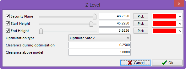
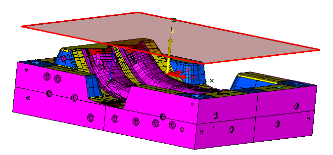
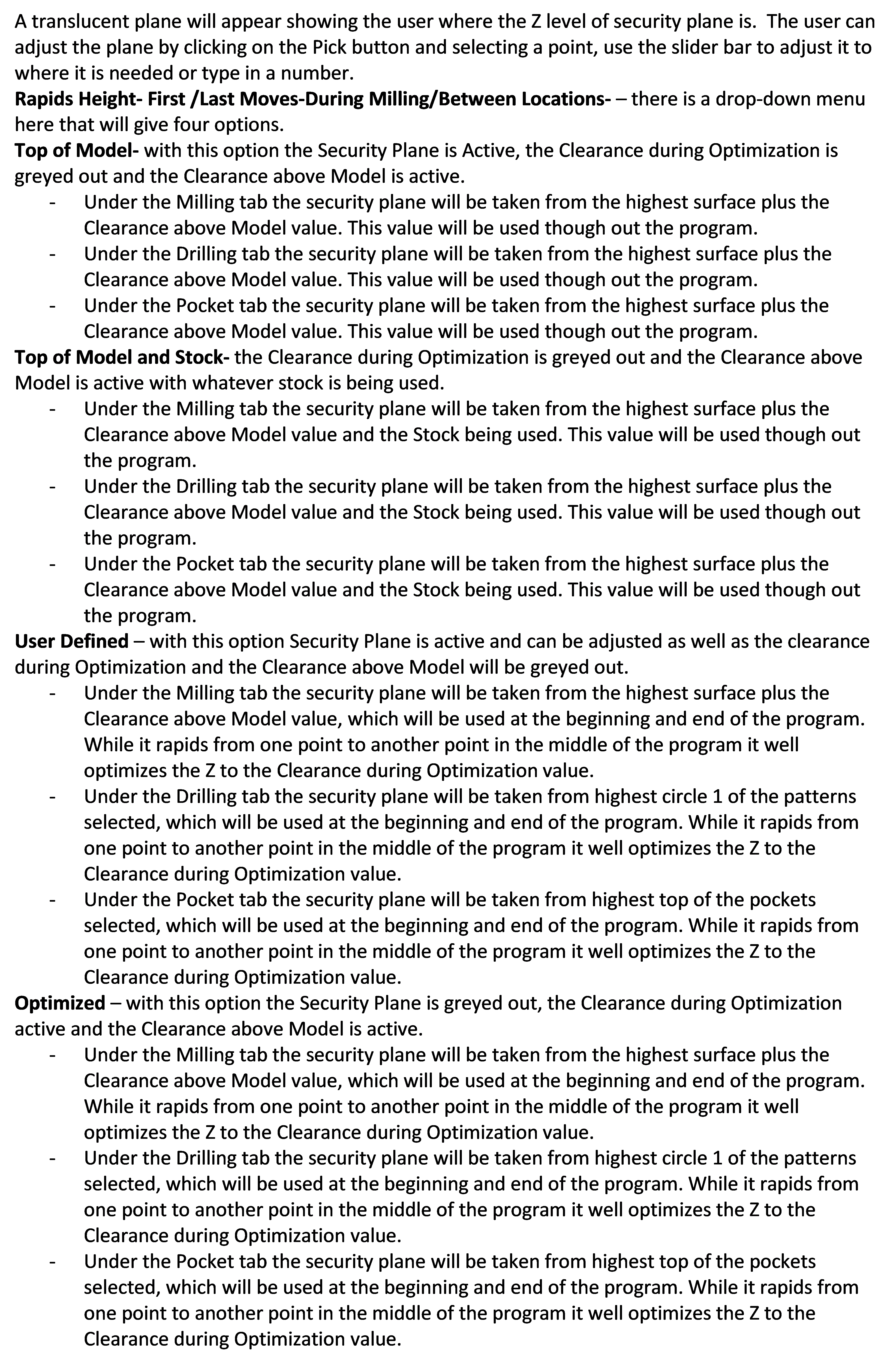
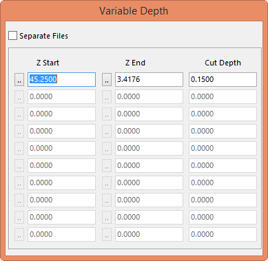
Variable Depth – will allow the user to change the depth of cut to different heights. By selecting this option, a secondary window called Variable Depth will be displayed.
In the first column will be the height the tool will start the cut, and the second column is where the cut will end. Once the end height has been entered, that value will default to the next start height in the next row. This will allow the user to use different length tools to complete the job. This option will also separate the programs to a predetermined name that can be changed later.
The third column will be the depth of cut the user wants to take in that section.
There is also a check box called Separate Files, with this box unchecked the program that is created will be one program. If this box is checked each row that is filled in will be its own separate program which will automatically be named.
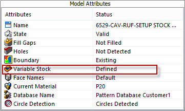
Variable Stock – this option is filed under the Model tab shown here. Right click on the Variable Stock to display the color palette. Fill in the stock allowances to leave on the color of choice. The user can leave different stock allowances on different colors.
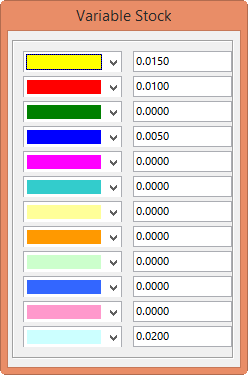
Checking this box in the Geometry Section will bring up the Variable Stock window that was filled in to show what stock allowance is assigned to what color. This option is only active if the box is checked.
1 Z Level Only – checking this box will create one pass at the Z level the user chooses. The upper part of the Geometry section will change and a button will appear asking for what Z level to create the single pass at. The user can also select the button and a secondary window will be displayed with a slider bar and a button to pick a point.

This will be the way the Geometry section will look

Pick a point or adjust the height with the slider bar.
Maximum Cornering Radius –the user can adjust the size of radius that the toolpath will create. This will help with chatter in the corners.
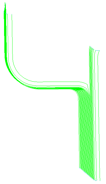 This is with the option unchecked
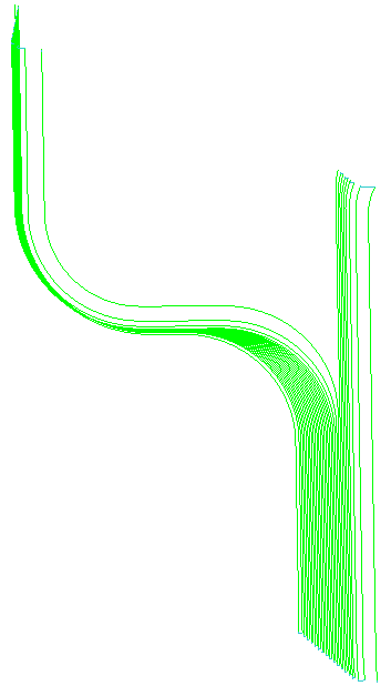 This is with the option checked and a value of 2.000 entered
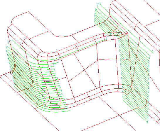
Stop on Contact - The user has the ability to choose the surfaces that are not to be cut. By selecting OK, the system will prompt the operator to select the surfaces not to be cut. Once chosen select OK.
When this option is selected the user will have a Filter Distance value that can be adjusted. This value will tell the system how far away to be from the surfaces that were chosen. Example on left.