meta data for this page
Display

Under the Display button there are many options to choose from to modify the look of the part or to turn things on and off.
These are the six different sections to modify the part.
Display Options

Under Display there is an option to turn things on and off to make it easier to view the part when needed.
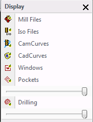
Mill Files, Iso Files, CamCurves, CadCurves, Windows, Pockets and Drilling are the options under this section.
Each one of these will either turn the display of them on or off. The icon picture next to the name will either have a green check mark or a red X. The green check mark indicates that the display of that item is on and the red X indicates that the display of that item is off.


Under Pockets and Drilling there are sliding bars that are used to make pockets or drill patterns more translucent. By sliding these bars to the left the shading on them will be less dense.

Selecting the External Boundary will turn it on and off.

This is used to turn the actual surface wireframe on and off. There is the option to also Hide all the UV surface lines.


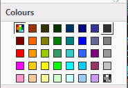
By selecting any of the colours in the colour palette the entire part will become that colour. To display the original colours select the multi coloured box in the top left corner of the colour palette.

This turns the stock model on and off. There is the option to make it more translucent by sliding the slider bar at the bottom to the left.