meta data for this page
Setup and References
 There are two options to help the user to set up data the same way that it is set up on the machine.
A setup is the way that the work piece is set up on the machine where a reference is an extension of that setup that lets the machine know what orientation it needs to be in on that setup.
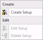 On the pull down menu for the setup option if there is no setup made at this point the only selection will be Create Setup. Clicking on this will bring up another window with more options.
Once a setup is made, the Edit Setup and Delete Setup will be enabled and they will allow you to edit or delete any setup you have.
These are the other options that will appear in the new window.

In this section the user can name the setup anything by typing in the name under Setup Name.
Table Face
Select the Table face button to let the system know which face of the job is on the machine table. Once the button is selected, run the cursor over the work piece and you will see it will give you faces to select from. Select the face that is on your machine table.
Origin Point
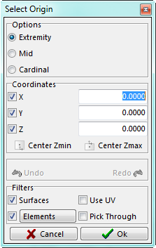
Selecting this option will give you a second menu where you can pick a point or type in the point where you wish your X, Y, Z zero’s to be.
There is also a Center Zmin and Center Zmax. This will find the center of all data on the screen and either put the coordinate system to the maxium or the minium of the data in the Z-axis.
You will also have the filter that allows you to only choose Surfaces, Elements or the UV lines of a Surface. It will also allow you to pick through the surfaces or only pick what is on top.


In this section the user is able rotate the job 90 degrees at a time to orientate the job the way it is on the table. For vertical machines it will rotate around the Z-axis, for horizontal machines it will rotate around the Y-axis.
In this section the user can give the system an alternate rotation point, where when programming it will rotate around that point. Select the Alt Rot Center button and a second menu will come up just like the Origin point selection menu. Marker Point will help to keep track of the orientation of the job by letting the user put a red ball at any point and if the job gets rotated or translated that marker ball will move with it.
The rest of the window is information about the job and machine.
Reference is an extension of the setup that tells the machine what orientation it needs to be in on that setup.

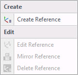
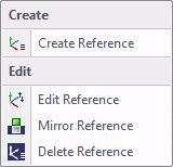
In order to create a reference, highlight the setup you wish to create the reference under, select the reference button, and a drop down menu will appear. The Edit, Mirror and Delete Reference selections will be greyed out. This is because the user told the system to make a new reference by having the setup highlighted. If an existing reference had been highlighted, then the Edit, Mirror and Delete Reference selections would have been active.
Once Create Reference has been selected, a second window with more options will appear.
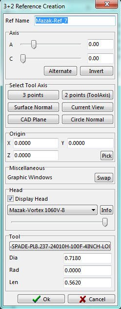
In this window there are seven sections of options that will aid the user in the creation of the new reference.
Ref Name
Axis
Select Tool Axis
Origin
Miscellaneous
Head
Tool
Each one of these serves its own purpose that will help in getting the reference needed to perform the task at hand.
Once Create Reference has been selected a window will appear in the top right hand corner of the screen. This window is a plan view to help visually create or edit a reference.
The head of the machine and a tool will appear on the screen, but only if the head of the machine exists.
We will explain how to create a reference and do so step by step. We need some of the elements in place to make it easier to create the reference.

The user can select the head of the machine if it has been created. Click on the None button and a list of heads will appear in a pull down menu where the user selects the desired head. With the Display Head check box there is the option of having the head displayed or not. Using the slider bar under the head name will make the head translucent. The Info button will give the information on the head.
Once the head has been selected, a tool then needs to be selected. The tool is only for visual purposes.
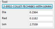
In the tool section click on the button and the tool database will appear. Select a tool that will give a good visual and will allow the user to properly see the angle that is trying to be achieved. Once a tool is selected place it anywhere on the job by picking any point and the head will move to that chosen point. This way the user can get right into corners to see if the tool or head will hit.
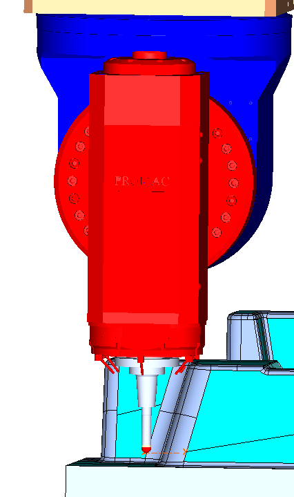
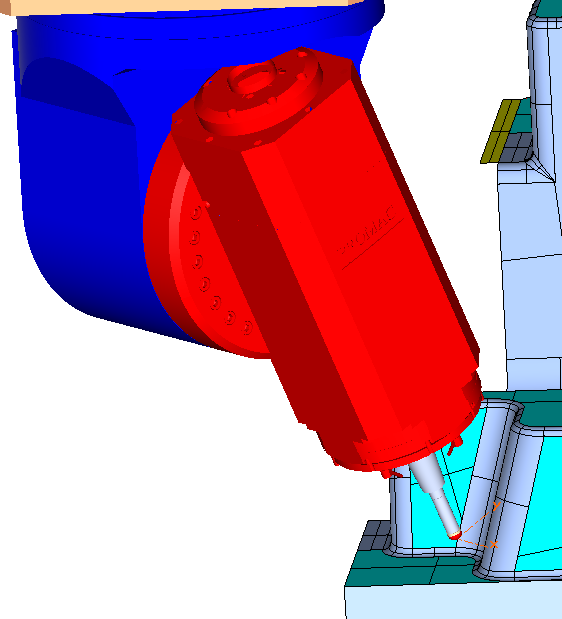

In this section the user can switch from the main window to the window that is in the top right corner of the screen. This gives the user the ability to have two different views and the ability to switch back and forth.

The ability to change the origin point for the reference being created. There is the ability to type in the position or pick a point. To pick a point click on the Pick button and a selection window will appear. This selection window will have all the filters of any selection window.

There are six options to select your tool axis.
3 points
The user will select three points. The first point is to let the system know the center of the X and Y axis. The second point will be the way the X-axis is to run from the first point selected. The third point will be the way the Y-axis to run from the first point selected. When done select the OK button and the reference is made.
2 points (Tool Axis)
For this option two points need to be selected to define the tool axis. The first point chosen will be where the tip of the tool is to be and the second point the direction the tool is to be.
Surface Normal
After selecting this option, pass the cursor over top of a surface. An arrow showing the direction to the tip of the spindle will be displayed. This will be the angle the head will be on.
Current View
Rotate the work piece into a view where the user would be looking down the axis of the tool. Click on the Current View button and that will be the new angle.
CAD Plane
Selecting this option will bring up another window which will have three option in it; XY, XZ and YZ. Selecting one of these planes will put the tool on that angle.
Circle Normal
Select any circle on the work piece and the tool will change to that angle.
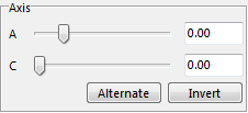
This is used to adjust the angle of the head by typing in the desired angles or use the sliding bar. At the same time the user can watch the head on the screen rotate to get the optimal angle needed. This will work for both axis.
Alternate – pressing this button will rotate the C-Axis 180 degrees for where it is. This way if the head of the machine is bulky on one side the user can have that portion of the head on the other side if needed.
Invert – This will invert the A-Axis angle to the opposite angle.

The system will auto name the reference according to the number of references given. The user has the ability to name the reference.