meta data for this page
3D Milling Tab

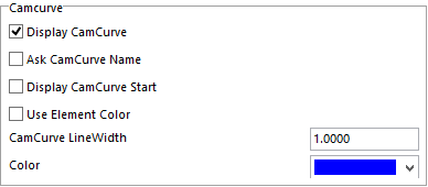
Display CamCurve – with this box checked the CamCurve will be displayed.
Ask CamCurve Name – with this checked, you will be asked to name the CamCurve after it is created.
Display CamCurve Start – with this checked a red dot will be displayed at the beginning of the CamCurve created.
Use Element Color – with this checked the CamCurve will be the same color of the element that was used to create the curve.
CamCurve LineWidth – here you can set the thickness of the CamCurve line.
Color – here you can set the default color of the CamCurves.


Window Line Width- Thickness of the window lines displayed.
Prompt for Window Name-When checked a box will appear for window name to be input.
Filter Islands for Surface Windows- Removes the Islands for the windows
This sets the default color of the engraving on the model.
These setting are specific to the 3D Milling tab.

A translucent plane will appear showing the user where the Z level of security plane is. The
user can adjust the plane by clicking on the Pick button and selecting a point, use the slider bar to adjust it to where it is needed or type in a number.
The color of the plane can also be changed by using the drop-down menu on the far right side next to the Pick button. It can also be turned on and off by checking or unchecking the box next to the name on the far-left side.
There are three ways the user can control how the tool will retract travelling from one area to the next. Once you have set these values and the type of Optimization, these settings will be the default for future programs made under the 3D Milling tab.
Optimization Type – there is a dropdown menu here that will give four options.
Top Of Model – is calculated using the “Box” dimension of the model in the operations CAM reference.
Top of Model + Stock – is calculated using the CAD model and active stock model.
User Defined- Will use whatever the operator types in for the security plane.
Optimized – allows the system to determine the best method for retracting to reduce travel.


Here you can set the default colors of these fields.
Here with this box checked all mill files that are created under the Drilling and Pocketing tabs will be displayed in the 3D Milling tab.
