meta data for this page
Geometry
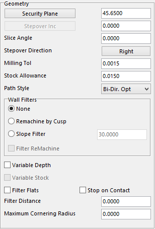
The Wall Filter section is also within the Geometry section which will be explained afterwards.
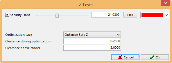
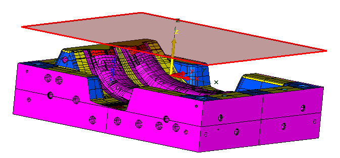
Security Plane – is the safe height that the user wants to start at.
Stepover Inc. – this value is the amount the user wants the tool to Stepover or the amount of material to take per pass.
Slice Angle – is the angle in which the tool will travel, 0.000 will be at 3 o’clock, and by increasing the value, the toolpath will move counter clockwise.
Milling Tol – this tolerance will help to determine the finish on the part. The smaller the value the more points on the toolpath.
Stock Allowance – is the value for how much stock the user wants to leave on the work piece.
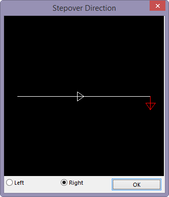
Stepover Direction – determines which way the cutter will step. Another window will display the direction the tool will step over. The arrows on the line will determine the direction the tool will travel. By selecting Left or Right it will change the direction of the arrows to show its new direction. If the Tool Path Angle is changed the line will change to show the true angle of the tool.
 Selecting this option will have a drop down menu that consists of these other options.
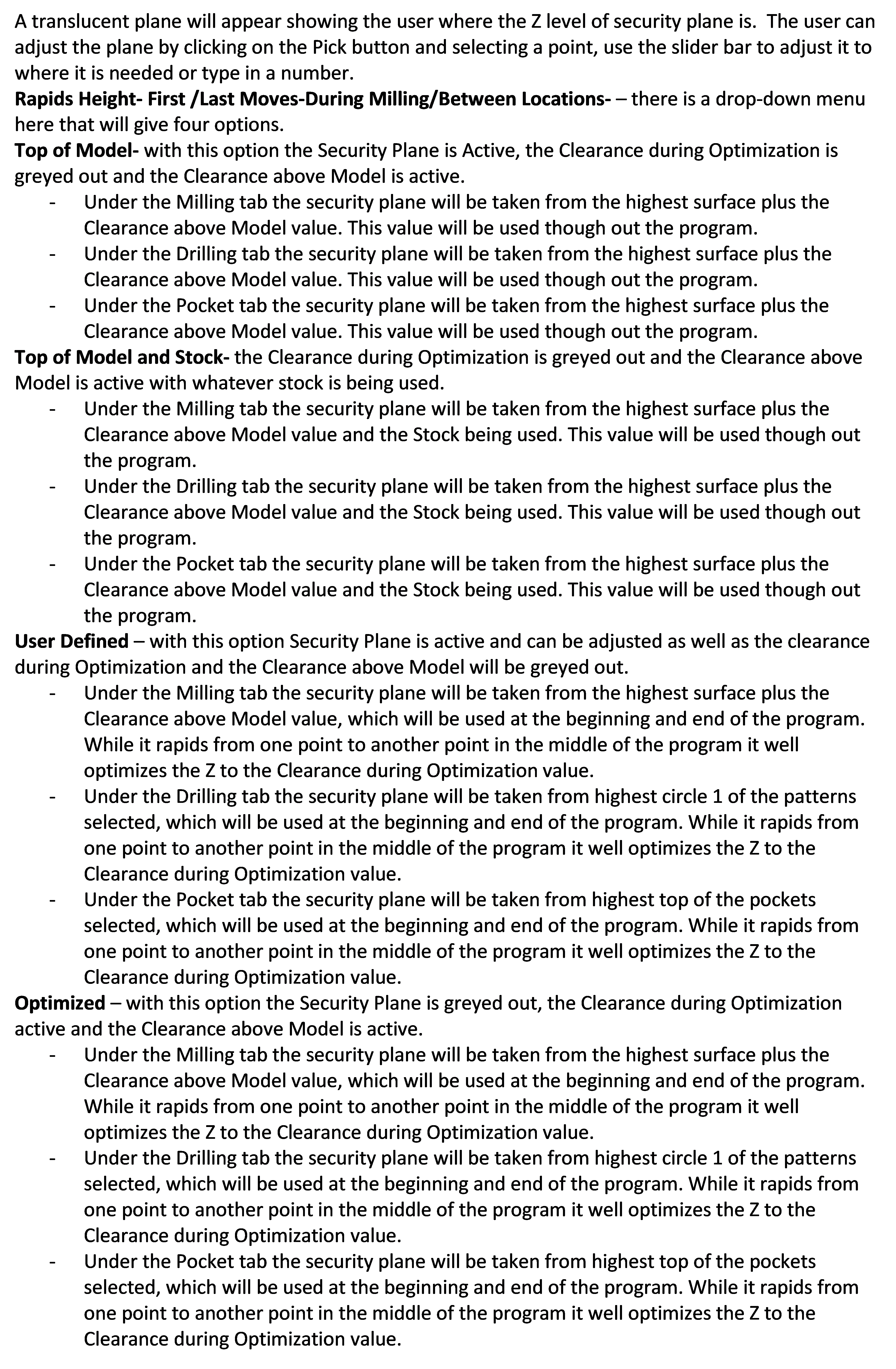
Bi-Dir. Opt –With this option selected when the tool travels from one pass to the other the tool will stay on the steel making it a more fluent toolpath. The black lines are the links from one pass to the next. Example to the left.
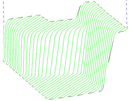
Bi-Dir. - The tool will move away from the work piece to go to the next pass if the tool is on an angle face. The black lines are the links from one pass to the next. Example to the left.
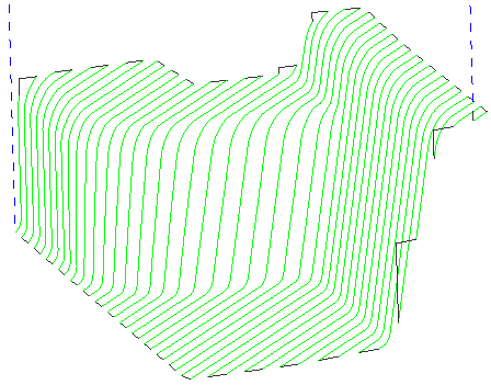
Uni-Dir. Opt –The tool will cut in one direction and rapid back to the start of the next pass to go in the same direction again. It will also optimize the rapid movements to only travel as high as needed to get there. The rapid moves are the blue dotted lines, and the black lines are the links or the start point of the cut. Example to the left.
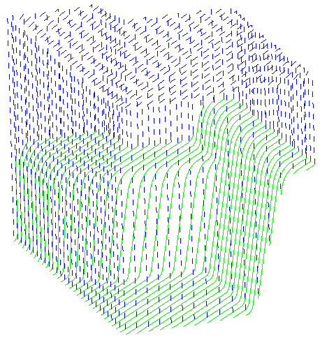
Uni-Dir. – The tool will cut in one direction and rapid back to the start of the next pass to go in the same direction again. It will go to the security plane to get to the start of the next pass. The rapid moves are the blue dotted lines, and the black lines are the links or the start point of the cut.
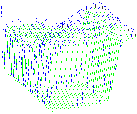
Top Down – With this option the tool will start at the highest point and cut the lowest point, rapid back to the top for the next pass, and go down again, at the same time optimizing the rapid. The rapid moves are the blue dotted lines and the black lines are the links or the start point of the cut.
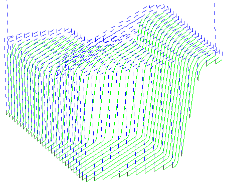
Down Top – With this option the tool will start at the lowest point and cut to the highest point, rapid over, and back to the lowest point to cut to the highest again at the same time optimizing the rapid. The rapid moves are the blue dotted lines and the black lines are the links or the start point of the cut.
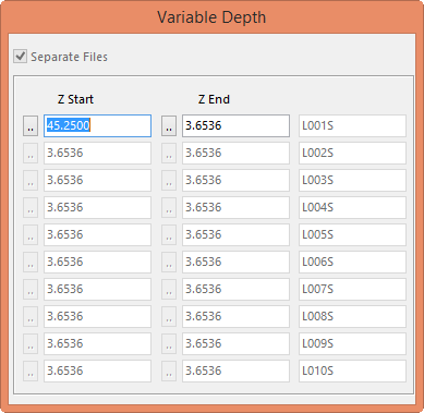
Variable Depth – will allow the user to change the depth of cut to different heights. By selecting this option, a secondary window called Variable Depth will be displayed.
In the first column will be the height the tool will start the cut, and the second column is where the cut will end. Once the end height has been entered, that value will default to the next start height in the next row. This will allow the user to use different length tools to complete the job. This option will also separate the programs to a predetermined name that can be changed later.
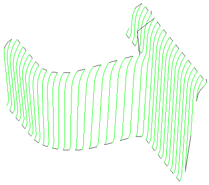
Filter Flats – With this option the system will avoid cutting any flat areas. This way if these areas were already cut with a flat operation they will not be cut twice. See example to the left.
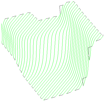
Minimum Cornering Radius –There are two different pictures to show the difference. In the first diagram the bottom radius is smaller than the second example. The first diagram has no value input and on the second picture there is a 2.000 value input.