meta data for this page
3D Milling Tab
The 3D Milling Tab gives the ability to create programs that will cut 3D contours for roughing, semi finishing, and finishing.
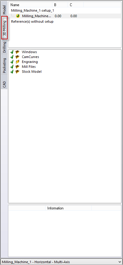
On the far left of the interface select 3D Milling tab. Once selected a new ribbon along with new left side information windows will appear.

Setup List displays all the created setup for this model. Select the individual setups to display options if available. If no setups are displayed, Right Click and choose Unhide.
Milling Entity Folder Tree contains the folder structure where milling elements are stored. By selecting any of these folders or the objects within them will display options specific to those items or folders. NC programs, Stock Model, Curves, Windows, etc. can be organized into separate folders in this panel.
The Toolpath Information panel displays information about the selected toolpath such as tool diameter, reference, window used, etc…

At the bottom of every side bar tab is the Machine Selector. If more than one machine has been defined in the machine configuration application, it will be listed in this pulldown menu. Make sure you have the machine selected you are programming for.