Holder Tab
Under this holder tab you will be able to create your holders, there are two different sections File and Holder.
File


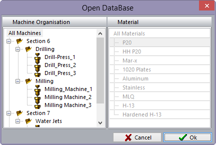
When you press the load icon you will have the following window pop up

In this window you will see all the machines and materials that you have setup under the Manufacturing Settings Module. Remember that in the Manufacture Settings you set permissions for all Users and only those Users that have permissions will have the ability to create holders or modify them. In order to input holders for all machines to see under Machine Organisation select All Machines and under Material select All Materials and select OK. This will open all holders that have been made or give you the ability to create new holders for all machines.
Holder


To keep your holders organized you can create folder tree to store your holders. To add a folder, highlight the folder then right click then click on Add Folder icon on the ribbon menu. The new folder will be displayed in the folder tree. The Folder can be renamed at any time. The user can enter as many folders as needed and can also have folders with in folders for further organization.


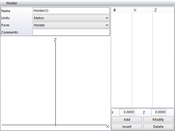
This icon will allow you to create holders, simply highlight the folder you wish to create the holder under and press this icon. A new section will appear to the right side of the interface for you to fill out.

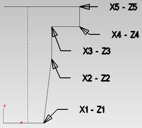
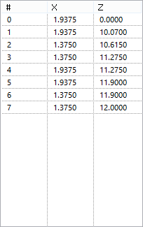
Now you need to type in the name of your holder and press enter, select the units of measurement you wish to use (Metric or Inch). Select what type of form you are creating, a holder or an extension are created the same way. The X will be the Radius of the holder section and the Z is distance from the tip of the holder. These values go on the same line to create a point in space to draw the holder. You will be able to watch the holder being drawn as you input the points. The design process starts at the tip of the holder to the spindle end of the holder (see picture below).


To input a point, fill in the X dimension and the Z dimension and click on the ADD button. If you have a dimension you wish to modify there are two ways to do it. You can click on the X or Z number you wish to change, change it and press Enter.

Click on the line number you wish to change and, in the X, or Z dimension box, type in the new dimension the click on the Modify button

To insert a dimension in between lines, click on the line below where you wish to insert it and type in the X and Z dimensions then click on the Insert button. To delete lines if needed by clicking on the line number and then clicking on the delete button.