Table of Contents
Head Tab
Under the head tab you will have the ability to import heads and configure them for your machine whether it be a 3-axis or a 5-axis machine. To start the load icon will be the only icon lite up on the ribbon. If you click on the load icon more of the ribbon will come to life.

Define Machine Head

This will load any head that has been saved in a RTM format

To keep your Heads organized you can create a tree of folders to store your Heads under. To add a folder simply have the folder that you wish to create another folder under highlighted and click on Add Folder on the Head section of the ribbon. It will come up with the folder icon the word Folder highlighted next to it, type in the name you wish the folder to be and press enter, you can have as many folders as you wish and you may also have folders under folders.

This allows you to shade the head or turn it into wire frame.
To get started create a folder to keep my Heads organized.

Next, I will select the Add Head icon, a window will come up simply find the RTM file that contains the head, select it and press Open. Under your folder the name of the file will appear, to keep things more organized and neater we suggest to name the head the same is the machine it goes with. You will also see that the head will appear graphically to the far-right side of the interface.
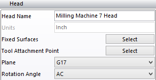
In the center of the head interface, you will see two sections Head and First Rotation Axis.
Head Options

In this section you will find
Head Name – Shows the name you have given the head, by double clicking on it you can change the name to anything you wish.
Units – It will default to the units the file was made in, inch or metric.
Fixed Surface – You need to press the select button and pick a part of the head that does not move for a multi axis head, if you have a 3-axis head you will need to select the whole head.
Tool Attachment Point – You need to press the select button and pick the point where the tool will attach to the head.
Plane – Here there is a drop-down menu which allows you to pick which plane the head will work in.
Rotation Angle – Allows you to pick the type of rotation your machine is, if you are using a multi axis machine, if the head you are using is not a multi axis head simply leave it on AC.
First Rotation Axis Options

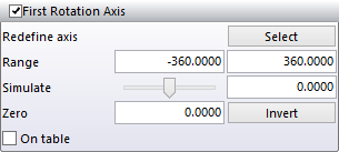
Next to the First Rotation Axis there is a Check box if the machine head you are creating has rotary axis you will need to check that box. You will now need to define the center of rotation and what part of the head will rotate, follow the instructions below to do this.
- Under redefine axis press on the select button, a window will come up you need to pick the point that is the center of rotation for that axis. Once that point is picked click on the right mouse button and another window will come up for you to select the part of the head that will rotate.
- Now you need to set the range the head is allowed to rotate, next to the Range there are two boxes. In the first box you need to set the negative value of the rotation in the second box you need to put the positive value of the rotation.
- You can now simulate the movement of the axis to see if it is good, if you click on the slide bar and move it back and forth you will see the axis you defined move. You can also type in a value you wish the axis to move to.
- Zero value
- Invert will change the negatives to positives and the positives to negatives
- On the Table
You may have noticed that an identical window has shown up below called Second Rotation Axis. If the head you are creating has a second rotation follow the same steps as the first rotation axis to do the second rotation axis.