RTM Tab Options

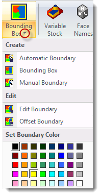
The Quick Access Ribbon contains some of the same options as in the Model Attributes Panel as well as many other options for working with the Model. The Icon with a black arrow indicates there is a pull down menu available with more options.
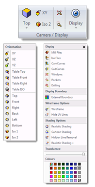
Camera/Display is a common section that is available in all the Side Bar tabs.
The first pull down menu contains all the View options and next to this is the Zoom Max and Zoom by Window functions.
The toggles for showing and hiding various entities in the display panel are also found in the Display pull down menu. As well as the Wireframe and Shading options, Translucence slide bar and the model display color palette.
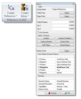
Reference (CAM) contains options to create machine setups and machining references. This group of options is available in all the Side Bar tabs except for the CAD tab.
Clicking on one of these options will open the Setup Editor tool.
When a model is imported from a CAD system RTM uses the original coordinate system. A setup can be created to reflect the actual setup on the machine leaving the original coordinate system unchanged.
The programmer can get which face of the work piece is on the table and where the X0 Y0 Z0 origin is located. The Select Tool Axis buttons have options to manually manipulate the axis system and options to use entities to determine the orientation of the axis system.
See Creating A Reference section for more info.
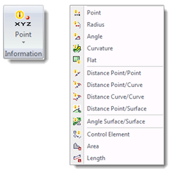
Information contains tools for measuring entities on the model. These options will display results from the current active reference.
For more information about the options in this section please refer to the Information, Measuring and Calculation section.

The Model section has many of the options from the Information Panel, clicking on any one of these will provide the same options.

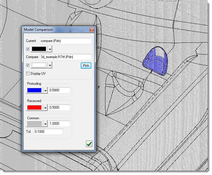
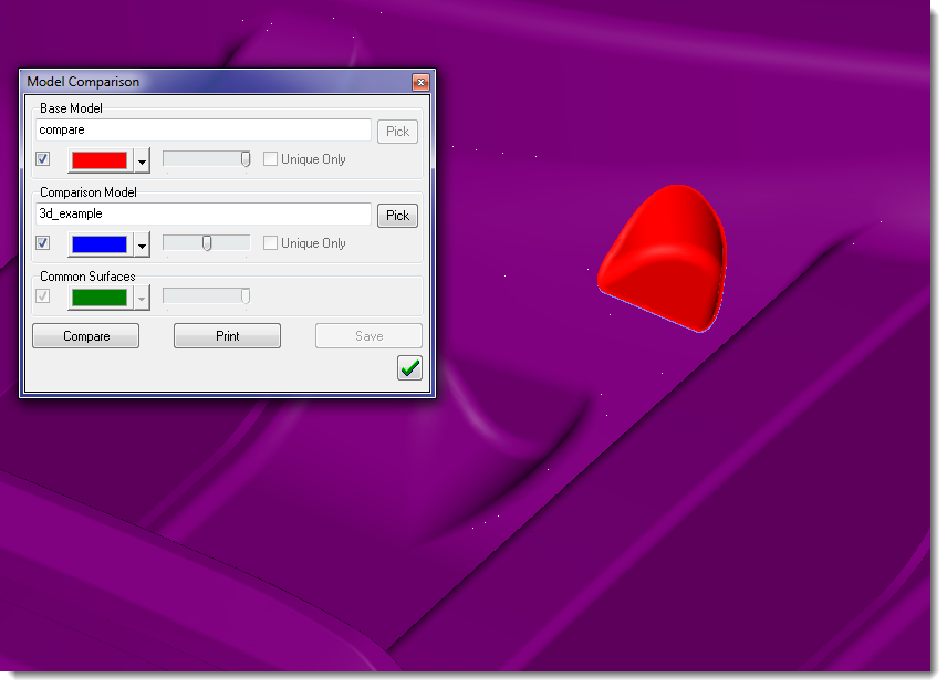
The Model Comparison Tool is used to compare 2 model against each other and display the differences or similarities.
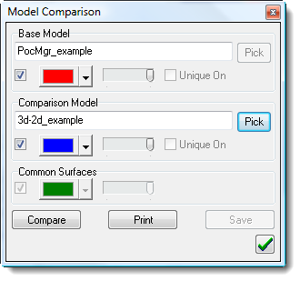
Surface Comparison – this option will compare two models using 3 separate define colors. One color will be for the first model, the next color will be for the second and the third color will display the common surfaces between the 2 models. This is a great tool to quickly check for differences or similarities between 2 models. Using the sliders will help to visually see the differences and similarities.
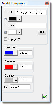
Graphical Comparison – this option will also compare 2 models, but this will graphically display the differences by color and by amount of difference determined by the user. It also has a separate color for common surfaces. This is a great tool to determine the amount of difference between two models, which would be helpful when determining the proper machining strategy.
Symmetric Model Test-Check to see if the model is symmetrical.
