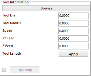
Tool Information Section

Choose the tool from the tool database which is what the Browse button is for. The data can also be manually inserted.
Tool Dia. - this is the tool diameter.
Tool Radius - this is the tool Radius; this will only show up in some operations.
Speed - this is the desired RPM of the tool used.
XY Feed - this is the desired milling feed rate for XY motion.
Z Feed - This is the desired feed rate for the Z motion.
Auto Tool Update – If you change parameter and want the changes to be permanent turn this off. If it is left on it will go back to the tool database to retrieve the parameters if they were changed.
Tool Length – if the apply button is pressed a second window will appear allowing the user to pick the next length of tool that they want to use to finish the operation. This button is only used for drilling and helical operations. There are some rules that do apply here to use it efficiently, that are explained below.

This is the window that will come up when the apply button is pressed. There are six columns for each tool selected. Once a tool is selected from the database some information will appear if the tool was created with this information. If the tool was not created with the information, it can be input manually.
Speed – is the spindle RPM.
Z Feed – is the feed rate.
Pitch – this the step down per revolution on a Heli operation.
Peck – will be the Peck depth in a Pecking operation.
Max Drill Depth – is the total depth that the tool is allow to go, this was setup in the tool database.
The first line will be the tool that you have selected in the main interface, to add more tools click on the browse to bring up the tool database. When the database comes up only the tools with the same diameter will appear for you to choose from.
Here are the rules for using the Tool Length option.
All the rule work from circle one, you must remember that the cut length also includes the Inc. Reach that is input on the assembly.
1 - If the cut length of the tool is shorter than the distance needed only one tool path will be created.
2 - If the cut length is shorter than the depth a second tool path will be created using the second tool in the tool length apply.
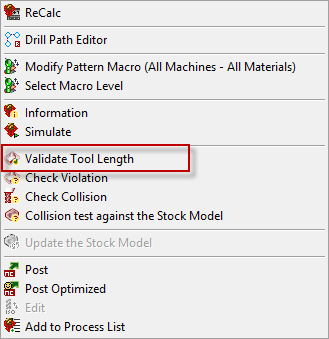
3 - If the cut length is shorter than the depth and there was no second tool selected, the tool path will still be created but a warning will come up telling you that the tool is to short. This will also change the status of the hole to Tool too Short, the system will create a tool path as deep as it is allowed but will not allow you to post the tool path. If you want to post the tool path you must validate Tool Length by right clicking on the mil file and select Validate Tool Length.
4 -The same will happen if second or three tool is to short.


Tip Comp
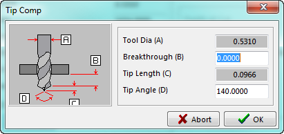
This option will allow the drill to go past the last circle by the tip of the drill. This can be set by the angle of the drill or by putting in a value. If you click on the Tip Comp button the following window will appear. There are two ways to change the amount that it goes past the last circle.
Input a value for the drill to go past the last circle in the Breakthrough (B) box. That distance will be added to the amount shown in Tip Length (C) box. The other way is to change the Tip Angle (D) . This is the included angle of the drill tip. The lower the angle, the deeper the drill will go past the last circle. The amount that the drill will go past the last circle will show up next to the Tip Comp button on the Tool Information section of the main programming interface.