Cad References

With the Cad option the user will be able to create References in order to create elements on different planes.
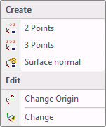
Selecting this option will open a drop down menu that allows the user options to create or choose different planes. The user will also have the ability to change the origin point.

With the 2 points option the user can change the vector of the Z axis.
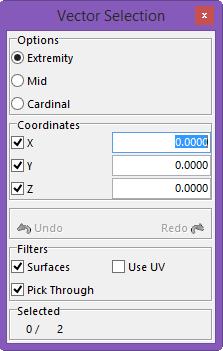
Once selected Vector Selection window will open and the user will select two points to determine the vector of the Z axis.
The first point will be the base of the vector and the second point will determine the direction.
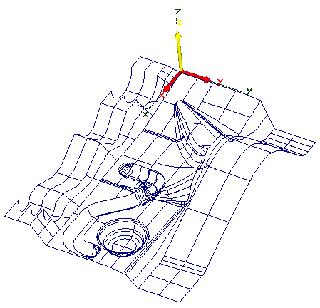
This is before selecting the 2 points; you can see the direction of the Z axis.
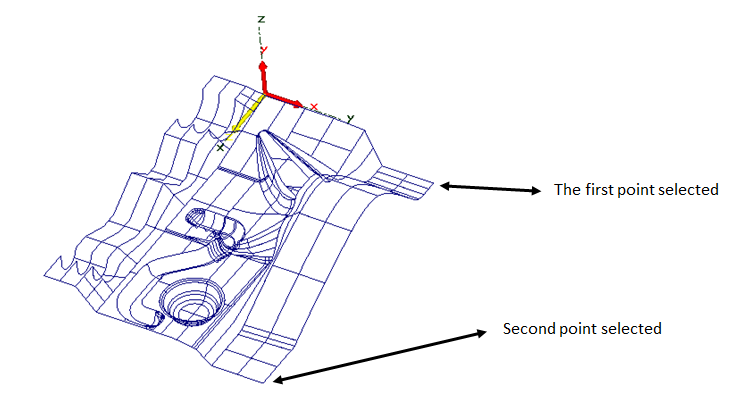
The direction of the Z axis has changed, the active coordinate system is red and yellow. The yellow is used for the Z axis and red for X and Y axis.

By using the 3 Point option the user can direct the Z axis into the direction needed.
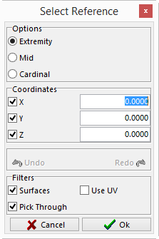
The Select Reference window will be displayed and the user will select four different points to complete the new reference.
First Point – the first point will be the beginning of both the X and Y axis.\\
Second Point – is the direction that the user wants the X axis to travel in relationship to the first point.
Third Point – is the direction that the user wants the Y axis to travel in relationship to the first point.
Fourth Point –if the user wants to change the original origin point it can be done so by selecting OK.
Before and after picture below.
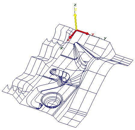 Before using 3 Points
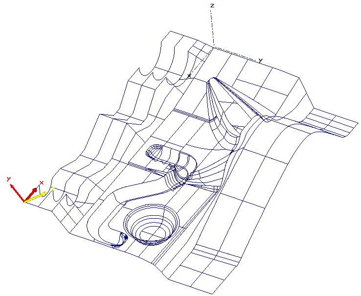 After using 3 Points and changing the origin point

By using this option, the user can use the surface to determine the direction of the reference.
When this option is selected the user will select the surface to use to create the reference.
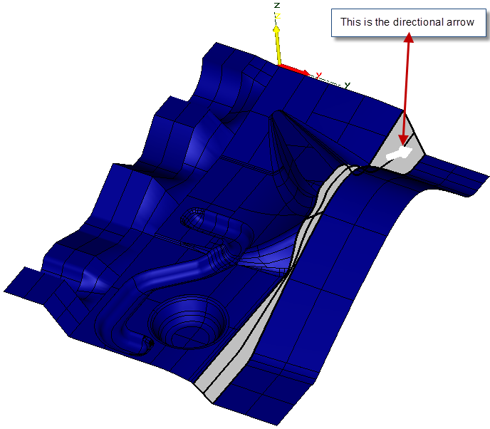
When the mouse passes over a surface it will change colors and a directional arrow will appear. This will show the user the direction that the Z axis will travel. If the arrow is pointing in the wrong direction the user can click on the right mouse button to make the arrow point in the opposite direction. Once the user has the surface and direction selected click the left mouse button to confirm.
Example is shown below.

This option allows the user to change the position of the origin making the XYZ zero in a different location.
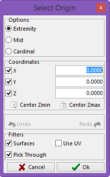
The Select Origin window will be displayed and the user can select the new location for the XYZ zero. Once selected, click the right mouse button to accept the selection and the coordinate system will move to that position.

This option allows the user to change from one reference to another.
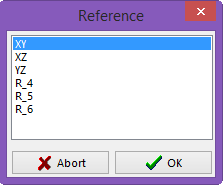
The Reference window will open and the user can select any reference that was made previously. Once the reference has been selected click on the OK button to activate the selected reference.