Leads and Links

In this section, select options to tell the software where and how to enter the steel.
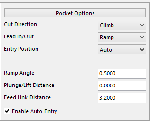
It consists of two areas, Pocket Options and Curve Options which each have different settings to configure. These will be displayed if using the stock model under Cutting Limits. If using Part Boundary or External Boundary the settings below will be displayed.
Pocket Option Setting
- Cut Direction
- Lead in/out
- Entry Position
- Ramp Angle
- Plunge/Lift Distance
- Feed Link Distance
- Enable Auto-Entry
Curve Option Settings
- Cut Direction
- Lead In/Out
- Arc Radius
- Arc Angle
- Plunge /Lift Distance
- Feed Link Distance

Cut Direction – select the direction to cut. Three options will be displayed, Climb Conventional and Both. If the Climb or Conventional options are selected it will cut in that way throughout the entire program even when cleaning all extra material. If Both is selected the program will determine the best way for the material to be removed and will cut in that direction.

Lead IN/Out – select how to enter the steel. Ramp, Heli and Plunge are the three options given.
Plunge – will plunge at a 90 degree angle into the steel.
Ramp – determines the angle for the tool to ramp in at. If Pocket Center or Input Point is selected the user can enter a Ramp Length.

Helical – this option will be displayed with other options for the diameter of the circle and the pitch which means depth/revolution.

Entry Position – three options to select from Auto, Pocket Center and Input Point.
Auto – with this option selected the program determines the point of entry automatically.
Pocket Center – this option will select the center of the pocket to use as a Entry Position.

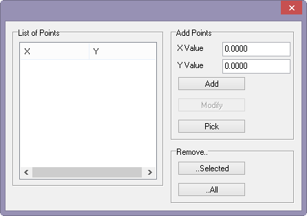
Input Point – with this option select the entry points for the tool. When selecting this option a second menu will be displayed and the user will need to enter or select points. To enter points simply type in the X and Y values and click on the add button. To select a point to enter simply click on Pick button and the user will be able to select a position on the screen with the aid of a sphere to help determine if the position is good. To remove a point, select that point and under the Remove section click on the selected button, or remove them all by clicking the All button.
Plunge/Lift Distance – this option allows the user to enter in a distance to start feeding from the point where it will contact the steel. If left at 0.000 the software will default to the value under the default button.