Geometry Section
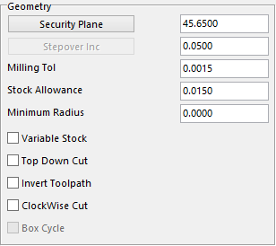
Security Plane – is the safe height that the user wants to start at.
Stepover Inc – this value is the amount the user wants the tool to Stepover or the amount of material he or she wants to take per pass.
Milling Tol – this tolerance will help to determine the finish on the part. The smaller the value the more points on the toolpath.
Stock Allowance – this value is the amount of stock that the user wants to leave on the top of the flat surface.
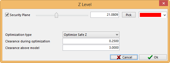
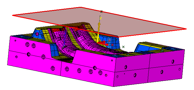
A translucent plane will appear showing the user where the Z level of security plane is. The user can adjust the plane by clicking on the Pick button and selecting a point, use the slider bar to adjust it to where it is needed or type in a number.
The color of the plane can also be changed by using the drop down menu on the far right side next to the Pick button. It can also be turned on and off by checking or unchecking the box next to the name on the far left side.
There are three ways the user can control how the tool will react travelling from one area to the next. Once you have set these values and the type of Optimization, these settings will be the default for future programs made under the 3D Milling tab.
Optimization Type – there is a drop down menu here that will give three options.
Respect User input – with this option Security Plane is active and can be adjusted as well as the clearance during Optimization and the Clearance above Model will be greyed out.
- Under the Milling tab the security plane will be taken from the highest surface plus the Clearance above Model value, which will be used at the beginning and end of the program. While it rapids from one point to another point in the middle of the program it well optimizes the Z to the Clearance during Optimization value.
- Under the Drilling tab the security plane will be taken from highest circle 1 of the patterns selected, which will be used at the beginning and end of the program. While it rapids from one point to another point in the middle of the program it well optimizes the Z to the Clearance during Optimization value.
- Under the Pocket tab the security plane will be taken from highest top of the pockets selected, which will be used at the beginning and end of the program. While it rapids from one point to another point in the middle of the program it well optimizes the Z to the Clearance during Optimization value.
Raise to Safe Z – with this option the Security Plane is Active, the Clearance during Optimization is greyed out and the Clearance above Model is active.
- Under the Milling tab the security plane will be taken from the highest surface plus the Clearance above Model value. This value will be used though out the program.
- Under the Drilling tab the security plane will be taken from the highest surface plus the Clearance above Model value. This value will be used though out the program.
- Under the Pocket tab the security plane will be taken from the highest surface plus the Clearance above Model value. This value will be used though out the program.
Optimize to Safe Z – with this option the Security Plane is greyed out, the Clearance during Optimization active and the Clearance above Model is active.
- Under the Milling tab the security plane will be taken from the highest surface plus the Clearance above Model value, which will be used at the beginning and end of the program. While it rapids from one point to another point in the middle of the program it well optimizes the Z to the Clearance during Optimization value.
- Under the Drilling tab the security plane will be taken from highest circle 1 of the patterns selected, which will be used at the beginning and end of the program. While it rapids from one point to another point in the middle of the program it well optimizes the Z to the Clearance during Optimization value.
- Under the Pocket tab the security plane will be taken from highest top of the pockets selected, which will be used at the beginning and end of the program. While it rapids from one point to another point in the middle of the program it well optimizes the Z to the Clearance during Optimization value.
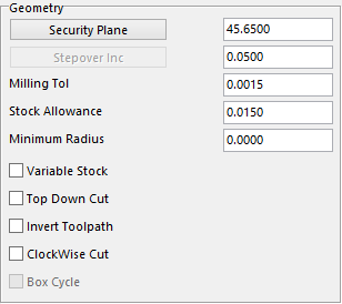
Minimum Radius – this option will put a radius on all sharp corners of the toolpath, example shown below.
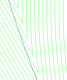 Here is an example of having the Minimum Radius value set to 0.000
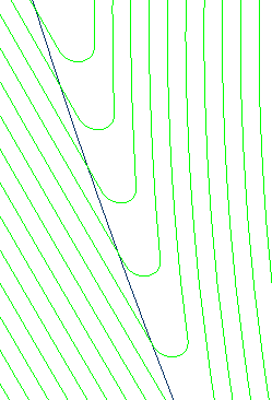 Here is an example of having the Minimum Radius value set to 0.050
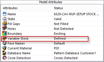
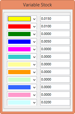
Variable Stock – – this option is filed under the Model tab shown here. Right click on the Variable Stock to display the color palette. Fill in the stock allowances to leave on the color of choice. The user can leave different stock allowances on different colors.
Checking this box in the Geometry Section will bring up the Variable Stock window that was filled in to show what stock allowance is assigned to what color. This option is only active if the box is checked.
Top Down Cut – with this option selected the tool will start at the highest point of the area selected, then start to go in a 3D step pattern from that point.
Invert Toolpath – with this option the user can make the toolpath start at the center of the toolpath and work its way outwards. Normally the toolpath will start at the outside edge and work its way inboard.
Clockwise Cut – the toolpath will normally travel in a counter clockwise direction. With this option checked the user can force the toolpath to go in the clockwise direction.